3-phase power network meter/analyzer ND1
$1,958.40
3-phase power network meter/analyzer ND1
Manufacturer: LUMEL
Product Code: ND1
- Description
- Size Guide
Description
PRODUCT DESCRIPTION
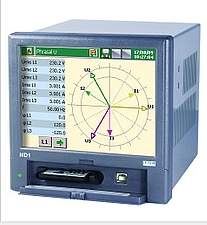
The ND1 3-phase power analyser is an up-to-date device allowing the user to measure and recording electrical energy quality parameters. It enables to detect interferences in internal industrial electric installations.
Product received also the prestigious award EUROPEAN MEDAL, which is granted for products, that fulfill legally required standards,
appropriate licenses and patents enabling their sale on the European market.
Data recorded by the ND1 analyser provide information for costs control systems and optimization o device operation in power energy installations and industrial systems.
The device design unites in itself the function of 5 instruments:
- analyser of 3-phase network parameters,
- universal measuring transducer,
- recorder of measuring data,
- web server – possible an easy remote monitoring of measuring and archival
- data through the internet browser
- controller – automatic control of electric energy key parameters.
The ND1 analyser-recorder is characterized by following features:
Measurement
Measurement and recording of electric energy quality parameters acc. to the EN 50160 standard, over 300 other parameters of 3-phase power networks, i.e.:
- phase voltages U1, U2, U3 and line currents I1, I2, I3,
- phase-to-phase voltages U12, U23, U31,
- phase active powers P1, P2, P3,
- phase reactive powers Q1, Q2, Q3,
- phase apparent powers S1, S2, S3,
- active power factors PF1, PF2, PF3,
- reactive/active power factors tgj1, tgj2, tgj3,
- mean phase-to-phase voltage US Umf,
- current in neutral wire and mean 3-phase current IO, IS,
- 3-phase active, reactive and apparent powers P,Q,S,
- mean 3-phase power factors PF, tgj,
- frequency f and frequency deviations,
- 15-minutes’ mean active power PAV,
- 3-phase active, reactive and apparent energy EnP, EnQ, EnS,
- active, reactive and apparent energy from an external counter EnPz, EnQz, EnSz,
- THD for phase and current voltages,
- harmonics of currents and phase voltages up to the 51st,
- storage of minimal and maximal values,
- recording of drops and voltage decays.
Data Recording
- Replaceable external CompactFlash memory of 4 GB capacity,
- Data storage in the internal 6 MB buffer with data supporting (before and after emergency states),
- Recording of decays and voltage drops acc. to the EN 50160 standard,
- Recording of selected measured parameters.
User’s Interface – GUI
- LCD TFT 5,7”, 320 x 240 pixels color screen, with touch screen panel,
- Casing protection grade from the frontal side: IP65
- Dedicated visualization in the shape of: digital displays, analog views, bargraphs, harmonic charts, vector diagrams, statistics, logic inputs
- Programming of the analyzer visualization ( selection of the measured quantity and kind of presentation),
- Contextual help in the user’s configuration menu.
Communication
- Ethernet 10 Base-T, Modbus TCP/IP,
- USB 1.1 Device,
- RS-485 Modbus Slave.
SPECIFICATIONS
Measured quantities and measuring ranges:
|
Kind of input |
Measuring range |
Parameters |
Basic error |
|
Voltage input |
57.7/100V, 230/400 V or 400/690 V |
0.05…1.2 Un |
± 0.2% |
|
Current input |
1A or 5A |
0.005…1.2 In |
± 0.2% |
|
Logic input |
12 inputs: 0/5…24 Vdc |
switch frequency up to 50 Hz |
|
|
Outputs |
|||
|
Output type |
Properties |
||
|
Analog output |
4 programmable current outputs of 0/4…20mA, |
||
|
Relay output |
• 6 programmable electromagnetic relays |
||
|
Output to supply object transducers |
• 2 ouptuts of 24 Vdc/30mA |
||
|
Digital Interface |
|||
|
Interface type |
Properties |
||
|
RS-485 |
2 interfaces: MODBUS slave and master, |
||
|
USB |
Device C.1.1, USBB-G socket |
||
|
Ethernet |
10 Base-T, RJ45 socket, Modbus Slave TCP/IP |
||
|
Rated Operating Conditions |
|||
|
Supply voltage |
85…230…253 V a.c./d.c., 40 .. 400 Hz or d.c. |
power consumption ≤ 30VA |
|
|
Ambient temperature |
Work: 0…23…50°C |
Storage: -20…60°C |
|
|
Relative humidity |
< 70% |
Condensation inadmissable |
|
|
Reaction against |
supply decays |
Data and device state preservation |
|
|
supply recovery |
Continuation of device work |
|
|
|
Short term load (5s) |
2 Un (max. 1000 V) |
10 In |
|
|
Casing protection grade |
From frontal side: IP 65 |
From terminal side: IP20 |
|
|
Safety requirements |
Installation catagory: II |
EN 61010-1 |
|
|
Pollution grade: 2 |
|||
|
Maximum phase to |
From the measuring system, |
||
|
For RS485 and USB |
|||
|
Measuring ranges and admissible basic conversion errors |
|||
|
Measuring quantity |
Range |
Basic error |
Remarks |
|
Voltage U |
57.73/100.0 V (Ku=1) |
± 0.2 % |
Ku = 1…4000 |
|
Current I |
1.000 a (kI=1) |
± 0.2 % |
Ki = 1…20000 |
|
Active power P |
0.0… (-) 6000,0 W |
± 0.5 % |
|
|
Apparent power S |
0.0…6000.0 VA |
± 0.5 % |
|
|
Reactive power Q |
0.0… (-) 6000.0 Var |
± 0.5 % |
|
|
Active power factor PF |
-1.000…0…1.000 |
± 0.5 % |
PF = Power |
|
Coefficient tgφ |
-10.00…0…10.00 |
± 1 % |
Ratio of active |
|
φ angle between U and I |
-180°…180° |
± 0.5 % |
Evaluated from |
|
Frenquency f |
45.00…66.00 Hz |
± 0.1 % |
|
|
THD U, THD I |
0.200.0% |
± 2 % |
Error in the range |
|
PST, PLT |
0…20 |
± 0.5 % |
in range of 0.05…35 Hz |
|
Active energy EnP |
0…(-) 99 999 999.9 kWh |
± 0.5 % |
|
|
Reactive energy ENQ |
0…(-) 99 999 999.9 kvarh |
± 0.5 % |
|
|
Where: |
|
|
Ku |
voltage transformer ratio |
|
Ki |
current transformer ratio |
|
THD U |
total coefficient of voltage harmonic distortion |
|
THD I |
total coefficient of current harmonic distortion |


