CURRENT TRANSFORMER TEST SET

$13,349.50
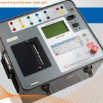
CURRENT TRANSFORMER TEST SET
Current Transformer Test Set with 1200 VAC excitation voltage
Manufacturer: Vanguard Instrument
Model: EZCT-10
P/N: 9045-UC (110Vac) /9046-UC (220Vac)

- Description
- Size Guide
- Vendor Info
- More Products
Description
CURRENT TRANSFORMER TEST SET

Current Transformer Test Set with 1200 VAC excitation voltage
OVERVIEW OF CURRENT TRANSFORMER TEST SET
The EZCT-10 is a microprocessor-based, current-transformer test set. This rugged and portable test set can perform the current transformer (CT) excitation, CT current-ratio, and winding polarity tests. Current transformers can be tested in their field-mounted configuration, eliminating the need to remove bushings or current transformers from the host equipment. The EZCT-10 uses a heavy-duty transformer to perform the CT excitation test. It is capable of outputting 50 Vac at 10A and 200 Vac at 10A.
- Perform Saturation, Ratio and Polarity Tests
- Fully Automated
- Comprehensive Graphic and Tabulated Test Reports
- Plot Multiple Saturation Curves
- Store 64 Records (of 10 Saturation Curves)
- Computer Interface
Excitation Test
The CT excitation test is performed using the ANSI/IEEE C57.13.1, IEC 60044-1 test method. The EZCT-10 applies an AC variable test voltage (up to 1,200 Vac) to the CT’s secondary windings. The EZCT-10 records and displays the test voltage and excitation current applied to the current transformer during the excitation test. Once tests are completed, up to 10 excitation curves and knee-point voltages of the tests can be plotted on the built-in thermal printer. ANSI 10/50, IEC 60044, IEC 61869, IEEE-30, and IEEE-45 knee point voltages are also calculated and printed on the test report.
CT Ratio and Polarity Tests
The EZCT-10 determines the CT current-ratio using the ANSI/IEEE C57.12.90 measurement method. A test voltage is applied on the CT’s X terminals and the induced voltage is measured across the CT’s H1 and H2 terminals. The current-ratio is displayed on the screen and stored in memory. The current-ratio measuring range is from 0.8 to 5,000. Winding polarity is displayed as a “+” sign (in-phase) or “-” sign (out-of-phase) and is annotated with the phase angle in degrees.
User Interface
The EZCT-10 features a back-lit LCD screen (4 lines by 20 characters) that is viewable in both bright sunlight and low-light levels. A rugged, alpha-numeric, membrane keypad is used to enter test information and to control the unit’s functions, and a voltage control knob is used to control the variable test voltage output. The test voltage range (50V at 10A, 200V at 10A, 1,200V at 1.5A) is selected with a switch on the control panel.
Built-in Thermal Printer
A built-in 4K” wide thermal printer can print the current transformer test report and plot the excitation curves.
Internal Test Record Storage
The EZCT-10 can store up to 128 current-transformer test records in Flash EEPROM. Each test record may contain up to 10 excitation curves, polarity, and current-ratio test data sets. Test records can be recalled and printed on the built-in thermal printer.
Computer Interface
The EZCT-10 can be used as a stand-alone unit or can be computer-controlled via the built-in RS-232C or USB interfaces. Windows®-based Current Transformer Analysis software is provided with each EZCT-10. This software can be used to retrieve test records from the EZCT-10 and can also be used to run CT tests from the PC. Tabulated test records can be exported in PDF, Excel, and XML formats for further analysis.
TECHNICAL SPECIFICATION
|
|||||||||||||||||||||||||||||||||||||||