")
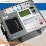
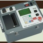
CURRENT TRANSFORMER TEST SET
$22,569.00
Manufacturer: Vanguard Instr.
Model.: EZCT-2000C

- Description
- Size Guide
- Vendor Info
- More Products
Description
CURRENT TRANSFORMER TEST SET

DESCRIPTION OF CURRENT TRANSFORMER TEST SET
The EZCT-2000C is Vanguard’s third-generation microprocessor-based current transformer test set. Designed specifically for CT testing, the EZCT-2000C has the following outstanding features that can greatly increase productivity and save time during the commissioning stage:
- Performs CT excitation, current-ratio, polarity, and phase angle tests
- Measures insulation resistance and winding resistance of the CT secondary windings
- Measures the CT’s load burden
- Standalone or computer-controlled via USB or Bluetooth wireless interface
The EZCT-2000C’s test leads can be connected to all the CT output terminals, and the complete CT test can be performed automatically without any operator intervention.
- Performs CT excitation, current-ratio, polarity, and phase angle tests
- Measures insulation resistance and winding resistance of the CT seconday windings
- Measures the CT’s secondary burden
- Test record header information including company, substation name, circuit ID, manufacturer, CT serial number, operator name, and test record-comments
- Built-in 4.5-inch wide thermal printer
- Plot Multiple Saturation Curves
- Stores up to 128 CT test plans and 140 test records internally
- USB, Bluetooth, and USB Flash drive interface
Excitation Test
The CT excitation test is performed using the ANSI/IEEE C57.13.1 test method. Test voltage ranges from 50, 300, 500,1200 and 2000 Vac can be selected for the excitation test. The test voltage is raised and lowered automatically by the EZCT-2000C. The excitation test voltage and current data is collected and stored in the unit’s internal memory. Knee point voltages (ANSI 10/50, IEC 60044, IEC 61869, IEEE-30, and IEEE-45) are calculated and printed on the test report. All of the test leads can be connected to the CT output terminals (X1, X2, X3, X4 and X5), and there is no lead switching required during testing. This convenient arrangement allows for testing any of the 10 possible combinations of X1 to X5. Up to 10 excitation tests can be stored in one record. Once the test is completed, the test report and CT excitation curves can be printed on the built-in thermal printer.
CT Winding Insulation Resistance Test Feature
The EZCT-2000C offers an IR test feature that can also measure the insulation resistance of the CT’s secondary winding using a test voltage up to 1000 Vdc. The DC winding resistance reading range is from 2 to 500 Mega-ohms. The insulation resistance test results are displayed and printed on the report.
Ratio and Polarity Tests
The CT current-ratio is determined using the ANSI/IEEE C57.13.1 Section 8.1 measurement method. A test voltage is applied on any two terminals (X1 to X5) of the CT, and the induced voltage is measured through the H1 and H2 terminals of the CT. The CT current-ratio is displayed and also stored in memory. The current-ratio is measured from 0.8 to 5,000. The CT winding polarity is displayed as a “+” sign (in-phase) or a “-” sign (out-of-phase) and is annotated with the phase angle in degrees. The CT current ratio error and phase displacement is also calculated based on the CT burden (or rated power) and rated current.
Demagnetization
The EZCT-2000C Plus automatically demagnetizes the CT under test when performing an excitation test. Winding
Resistance Test
The EZCT-2000C can measure the DC resistance of transformer windings from 100 micro-ohms to 10 ohms.
CT Burden Test
The EZCT-2000C can measure the CT’s actual connected burden by injecting a 1A or 5A test current into the load. The CT burden measurements (Voltage, current, Cos φ, and burden impedance) are displayed on the screen and printed on the test report. This important test verifies the actual CT measured burden before putting the CT in service, thus avoiding any potential configuration conflicts.
Current Ratio and Phase
As part of the tabulated test results, the EZCT-2000C can also print the current ratio and current phase error tables.
Current Source
The EZCT-2000C offers a programmable current source (0-20A, 0-15Vac) that can be used to verify CT loads. The on-time timer and output current are displayed on the LCD screen.
SPECIFICATIONS
| TYPE | Portable current-transformer test set |
| PHYSICAL SPECIFICATIONS | 19″W x 13″H x 16″D (48.3 cm x 33cm x 40.1 cm); Weight: 73 lbs (33.1 kg) |
| INPUT POWER | 100 – 120 Vac or 200 – 240 Vac (factory pre-set), 50/60 Hz |
| MEASUREMENT METHOD | IEC 60044-1, IEC 61869, ANSI/IEEE C57.13.1, and ANSI/IEEE C57.12.90 |
| TEST OUTPUT VOLTAGES | 0 – 50 Vac @ 10A max 0 – 300 Vac @ 10A max 0 – 500 Vac @ 5A max 0 – 1200 Vac @ 1.2A max 0 – 2000 Vac @ 1A max |
| CURRENT SOURCE | 1 – 20A @ 0 – 15 Vac |
| CURRENT SOURCE DISPLAY | Test current and current on-time |
| VOLTAGE READING RANGE | 0 – 2,200 Vac; Accuracy: ±1.0% of reading, ±1 V |
| CURRENT READING RANGE | 0 – 10A; Accuracy: ±1.0% of reading, ±0.02A |
| CT CURRENT RATIO RANGE | 0.8 – 999: ±0.1% 1000 – 1999: ±0.3% 2,000 – 4,999: ±1% 5,000 – 10,000: ±1.5% |
| PHASE ANGLE MEASUREMENT | 0 – 360 degrees; Accuracy: ± 1.0 degree) |
| RESISTANCE READING RANGE | 100 micro-ohms – 30 ohms; Accuracy: 2% of reading, ± 1 count, ± 10 micro-ohms |
| INSULATION RESISTANCE READING RANGE | 2 Mega-ohms – 500 Mega-ohms; Accuracy: 3% of reading, 500 – 1000 Vdc test voltage |
| DISPLAY | Back-lit LCD Screen 240 x 128 pixels; 114mm x 64mm Viewable in bright sunlight and low-light levels |
| PRINTER | Built-in 4.5-inch wide thermal printer |
| COMPUTER INTERFACES | One USB port and Bluetooth wireleass interface |
| EXTERNAL DATA STORAGE | One USB Flash drive interface port (Flash drive not included) |
| PC SOFTWARE | Windows®-based CT Analysis software is included with purchase price |
| INTERNAL TEST RECORD STORAGE | Stores 140 test records. Each test record may contain up to 10 sets of excitation, resistance and ratio data |
| INTERNAL TEST PLAN STORAGE | Stores 128 test plans. Each test plan can store 10 excitation test voltage and current settings |
| SAFETY | Designed to meet UL 61010A-1 and CAN/CSA C22.2 No. 1010.1-92 standards |
| ENVIRONMENT | Operating: -10°C to +50°C (+15°F to +122°F); Storage: -30°C to +70°C (-22°F to +158°F) |
| HUMIDITY | 90% RH @ 40°C (104°F) non-condensing |
| ALTITUDE | 2,000 m (6,562 ft) to full safety specifications |
| CABLES | One 20-foot cable set (X1-X5), one 35-foot H cable set, current source cables, insulation test cables, power cord, ground cable. A transportation case is included with the purchase price |
| WARRANTY | One year on parts and labor |