DC Signal Transducer With Data Logging, P30H


$297.30
Manufacturer: LUMEL
Product Code: P30H

- Description
- Size Guide
- Vendor Info
- More Products
Description
DC Signal Transducer with Data Logging, P30H
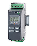
Description of DC Signal Transducer With Data Logging, P30H
P30H measures and records current, voltage, power, energy and other d.c. circuit parameters.
The output signal is galvanically isolated from the input signal and the power supply.
P30H has programmable measurement and additional functions.
Programming parameters can be realized with the use of buttons, via RS-485 interface and free e-con software or Ethernet
Transducer is available in 3 versions:
- basic,
- with SD/SDHC card,
- with Ethernet and internal file system memory.
Features and functions:
- Programmable input
- DC parameters
- current via shunts +/- 150mV
- voltage 0…12/48/100/250V or 0…600/1000V with additional resistor
- Output:
- 1 x analog 0/4…20mA or 0…10V
- 1 x relay, optionally changeable to 0/4…20mA or 0…10V analog output
- 1 x additional relay, optionally changeable to 0…24V d.c. supply output
- LCD 2 x 8 characters with LED backlight
- Supply: 85..253 V a.c./d.c. or 20…40 V a.c./d.c., / 20…60 V d.c.
- Conversion of measured values into an output signal on the base of the individual linear characteristic
- 1 or 2 alarm relays with NO contact operating in 6 modes
- Additional supplying output 24 V d.c 30 mA switched-on/switched-off (option).
- Recording of input signals in internal file, on SD/SDHC card (option) or internal file system memory (option).
- Interface RS-485 Modbus RTU.
- RS-485 Master/Monitor mode – possibility to poll 1 device.
- SD/SDHC support (option).
- Interface Ethernet 10/100 BASE-T (option).
- Protocol: Modbus TCP/IP, HTTP, FTP.
- Services: www server, ft p server, client DHCP
- Dimension: 45 x 120 x 100mm
SPECIFICATION
|
Measured and calculated values by the transducer |
|
|
● d.c. voltage U (direct or through additional resistor D5) ● d.c. current I (direct through shunt) ● power of d.c. current P ● voltage difference in time dU (5 s, 30 s, 1 min, 5 min or 15 min) ● current difference in time dI (5 s, 30 s, 1 min, 5 min or 15 min) ● voltage averaged over time UAV (15, 30 or 60 min.) ● current averaged over time IAV (15, 30 or 60 min.) ● power averaged over time PAV (15, 30 or 60 min.) |
● operating/ measurement time t [s] ● operating/ measurement time t [H.M] ● load capacity C ● input energy EP← ● output energy EP→ ● total energy EP (input+output) ● maximum and minimum values |
|
Inputs and measuring ranges |
||||
|
Measured time |
Nominal range KU=1, KI=1000 |
Measuring range (maximum) |
Class |
|
|
Voltages U, DU, UAV |
12 V |
-4…12 V |
-5…15 V |
0.2 |
|
48 V |
-4… 48 V |
-10…57.6 V |
||
|
100 V |
-5…100 V |
-10…120 V |
||
|
250 V |
-5…250 V |
-10…300V |
||
|
600 V* |
-10…500 V |
-10…600 V |
0.2 + additional resistor |
|
|
1000 V* |
-10…1000 V |
-10…1000 V |
||
|
Currents (shunt voltage) I, DI , IAV |
-150…150 A (-150…150 mV) |
-180…180 A |
0.2+ shunt class (voltage measurement 0.2) |
|
|
Time counter T[S] |
0…999999999 s 0…277777.5 h.m |
1s/ 24h, |
||
|
Capacity C |
-92 233 720 368…92 233 720 368 kAh |
±5 % |
||
|
Power P, PAV |
12 V |
-0.6…1.8 kW |
-0.75…2.25 kW |
0.4 + shunt class |
|
48 V |
-0.6…7.2 kW |
-1.5…8.64 kW |
||
|
100 V |
-0.75…15 kW |
-1.5…18 kW |
||
|
250 V |
-0.75…37.5 kW |
-1.5…45 kW |
||
|
600 V* |
-1.5…75 kW |
-3…90 kW |
0.4 + shunt class + + class of additional resistor |
|
|
1000 V* |
-3…150 kW |
-6…180 kW |
||
|
Input energy EP |
0…99 999 999,9 kWh |
±5 % + shunt class |
||
|
* – version in set with additional resistor D5 (Ku≠1), KU – voltage ratio (Primar.U/Second.U), KI – current ratio (Shunt I/Shunt mV, KI = 1000 e.g. for shunt 150 A/150 mV) The maximum range display of measured values on the LCD display are -99999G…99999G. |
||||
Vendor Information
-

-
 Air Monitoring & Sampling, Dust & Aerosol Detection & Monitoring, Environmental Quality & Occupational health Monitoring, Featured, Handheld Dust detective Instrument – Microdust Pro, Instrumentation Products, Personal Sampling Pumps – Apex, Portable Dust detective kits, Promotion, Remote Dust monitoring system, Remote Multi Parameter (Noise & Dust) Monitoring System
Asbestos TEM cassette with 0.45um MCE membrane
$0.00