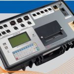
Digital Circuit Breaker Analyzer 3-Main Contact model

$18,454.43
Digital Circuit Breaker Analyzer 3-Main Contact model
Manufacturer: Vanguard Instrument
Model: CT-7000 -S3-3
P/N: 9021-UC

- Description
- Size Guide
- Vendor Info
- More Products
Description
Digital Circuit Breaker Analyzer 3-Main Contact model
Description of Digital Circuit Breaker Analyzer 3-Main Contact model
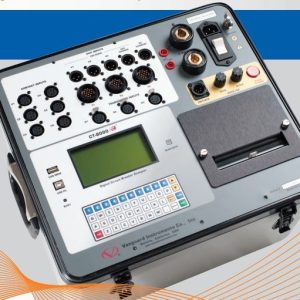
The CT-7000 S3 is Vanguard’s fourth generation EHV circuit breaker analyzer. The CT-7000 S3 is available with 3 (part number 9021-UC) or 6 contact timing channels (part number 9100-UC). The CT-7000 S3 can fully analyze a circuit breaker’s performance by measuring the main contact and resistor contact time, stroke, velocity, over-travel, bounce back and contact wipes. Both contact and motion analysis can be performed on all circuit breaker operations (OPEN, CLOSE, OPEN-CLOSE, CLOSE-OPEN, and OPEN CLOSE-OPEN). The CT-7000 S3’s timing window is selectable between 1 second, 10 seconds, and 20 seconds.
- Fully analyze circuit breaker’s performance by measuring main contact and resistor contact time, stroke, velocity, over-travel, bounce back and contact wipes
- USB computer interface
- USB Flash drive interface (Flash drive not included)
- Store up to 200 test records and 100 test plans internally
- Initiate Breaker Operation
- Built-in 4.5″ wide Thermal Printer
- Rugged “QWERTY” style membrane keypad
- Optional “On-line” Timing Mode
- Optional dual ground testing mode
- Optional Bluetooth wireless computer interface
Contact Timing Inputs
The CT-7000 S3’s dry contact timing channels (up to 6 channels) are used to time the circuit breaker main contacts. Each main contact timing channel is capable of detecting the main contact and insertion resistor contact time. Timing results are displayed in milliseconds and cycles.
Breaker Stroke and Velocity
Three dedicated digital travel transducer channels are available on the CT-7000 S3 for measuring circuit-breaker contact stroke, velocity, over-travel, and bounce back. With the use of the Vanguard digital travel transducers, neither calibration nor setting is required. Circuit breaker contact velocity is calculated based on contact’s travel distance over a period of time. Special formulas to calculate velocity is also accommodated by the CT-7000 S3. A special feature is also available to “Slow-Close” test the circuit breaker and obtain a test result report.
Resistor TypeTransducer Input
The CT-7000 S3 offers 3 resistor type transducer input channels. These input channels are used to interface with any resistor-type transducers to monitor the circuit breaker motion. Transducer resistance ranges from 200 Ohms to 10K Ohms.
Voltage Monitoring Channels
The CT-7000 S3 features three voltage monitoring input channels (V1, V2, and V3). The V1 voltage channel is dedicated to monitoring the substation DC supply or coil voltage (0-255 V, DC or peak AC). The nominal and minimum DC supply voltage levels are recorded and printed on the tabulated report. An analog waveform showing the DC power supply is plotted on the graphical report. The two digital voltage input channels, V2 and V3, are dedicated to monitoring voltage on/off status presence or absence of the circuit breaker auxiliary switches. Digital waveforms showing V2 and V3 activity are plotted on the graphical report. Three timing events of the V2 and V3 activities are recorded and printed on the tabulated report.
OPEN/CLOSE Coil Current Monitoring
One built-in, hall-effect sensor records the OPEN/CLOSE coil current amplitude and waveform. The circuit breaker’s coil current waveform, effectively, a coil performance “fingerprint” or “current profile”, can be used as a diagnostic tool for analyzing the circuit breaker’s performance.
Breaker Initiate Features
A built-in solid-state initiate device is used to operate a breaker from the CT-7000 S3. Operational modes include OPEN, CLOSE, OPEN-CLOSE, CLOSE-OPEN, and OPEN-CLOSE-OPEN. Multiple operation like OPEN-CLOSE, CLOSE-OPEN, and OPEN-CLOSE-OPEN can be initiated by using a programmable delay time (in milliseconds) or by sensing a specific breaker contact condition. The circuit breaker coil current amplitudes and waveforms are recorded and can be printed on the thermal printer.
Computer Interface
The CT-7000 S3 can be computer-controlled via the USB or optional Bluetooth interface. Windows-based Circuit Breaker Analysis Software is provided with each unit. Using this software, circuit breakers can be timed from the PC. Test records can be retrieved from the CT-7000 S3 and then stored on the PC for future analysis and report generation. Circuit breaker test plans can also be created on the PC and transferred to the CT-7000 S3. Additionally, test records can be automatically exported in Excel, PDF, and XML formats.
Built-in Thermal Printer
The CT-7000 S3’s built-in 4.5″ wide thermal printer can print the breaker contact analysis results in both tabular and graphic formats.
SPECIFICATIONS
| TYPE | Portable circuit-breaker analyzer |
| PHYSICAL SPECIFICATIONS | Dimensions: 21.5”W x 8”H x 14” D (53 cm x 20 cm x 35 cm) Weight: 15 lbs (6.8 Kg) |
| INPUT POWER | 100-240Vac, 3A, 50/60Hz |
| DRY-CONTACT INPUTS | 3 channels (9021-UC) or 6 channels (9100-UC). Channel can detect the main contact and resistor contact time. |
| TIMING WINDOWS | 1 second, 10 seconds, or 20 seconds |
| TIMING RESOLUTIONS | ±50 micro-seconds @ 1 sec. duration, ±500 micro-seconds @ 10 sec. duration, ±1.0 milli-seconds @ 20 sec. duration |
| TIMING ACCURACY | 0.05% of reading ±0.05 ms @ 1 second duration |
| DRY-CONTACT CHANNEL PROTECTION | All contact inputs are grounded until test. Input channels are also protected against static discharge. |
| DRY-CONTACT DETECTION RANGE | Closed: Less than 20 Ohm. Opened: greater than 5000 ohm |
| INSERTION RESISTOR DETECTION RANGE | 50 – 5,000 ohms |
| TRIGGER INPUT VOLTAGE | Open/Close trigger voltage: 24 V – 300V DC or peak AC |
| VOLTAGE SENSING INPUT RANGE | V1: analog input; 0 – 250 V DC or peak AC; sensitivity ±1 V; record and print voltage level V2 and V3: voltage presence/absence detector input; 24 – 255 V DC or peak AC; record and print 3 timing events |
| BREAKER OPERATIONS | Initiate Open, Close, Open-Close, Close-Open, Open-Close-Open |
| BREAKER INITIATE CAPACITY | 30A, 250 Vac/dc max |
| INITIATE CURRENT READING RANGE | one, non-contact, Hall-effect sensor, 0 – 20 amp range, dc to 5 Khz AC |
| DIGITAL TRAVEL TRANSDUCER INPUTS | 3 channels, 200 ohm – 10K ohms |
| CONTACT TRAVEL POINT DIFFERENCE | measures “slow-close” contact-point distances; results can be printed |
| DISPLAY | back-lit LCD screen (128 x 240 pixels); viewable in bright sunlight and low light |
| PRINTER | built-in 4.5” wide thermal printer that can print both graphic contact travel waveforms and tabulated test results |
| INTERNAL TEST RECORD STORAGE | Store up to 200 test records and 100 test plans |
| EXTERNAL TEST RECORD STORAGE | USB Flash drive interface for external storage of test records and test plans |
| COMPUTER INTERFACES | One USB port, optional Bluetooth wireless interface |
| PC SOFTWARE | Windows® based Breaker Analysis software included with purchase price |
| CABLES | furnished with full set of test leads |
| OPTIONS | transportation cases (available for the CT-7000 S3 and travel transducers), on-line timing mode, dual ground testing mode, bluetooth interface |
| SAFETY | designed to meet UL 6101A-1 and CAN/CSA C22.2 No 1010.1-92 standards |
| ENVIRONMENT | Operating: -10°C to +50°C (+15°F to +122°F); Storage: -30°C to +70°C (-22°F to +158°F) |
| HUMIDITY | 90% RH @ 40°C (104°F) non-condensing |
| ALTITUDE | 2,000 m (6,562 ft) to full safety specifi cations |
| WARRANTY | one year on parts and labor |
| Specifications are valid at nominal voltage and ambient temperature of +25˚C (+77˚F). | |
Vendor Information
-

-
 Environmental Quality & Occupational health Monitoring, Handheld Sound Level Meter, Instrumentation Products, Noise Monitoring & Recording, Portable Noise Nuisance Recorder, Remote Multi Parameter (Noise & Dust) Monitoring System, Remote Noise Monitoring System
Logging Sound Level Meter Class 2
$2,208.94 -

-